MAGNETIC DRIVEN INTERNAL ECCENTRIC GEAR PUMP
| PUMP PROPERTIES | |||
| Q | : 0,100 – 55 m³/h | T | : 20 ~ 250 ºC |
| Hm | : 1 ~ 12 Bar | n | : 20 – 1750 d/d |
| Visc. | : 100 ~ 25.00 SSU | ||
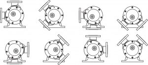
Magnetic Driven Internal Eccentric Gear Pump Types


Product Features
Internal eccentric gear pumps with magnetic coupling play a critical role in various industrial applications. These pumps realize fluid flow in a continuous and controlled manner with the positive displacement principle, ensuring safe transport of viscous and abrasive fluids. The magnetic coupling provides the sealing between the motor and the gear system. This prevents fluid from leaking out, minimizing environmental pollution and safely risks. By preventing leaks, the design prevents contamination of the fluid, which is particularly important in the food, chemical and pharmaceutical industries.
Pumps can operate at different speeds and pressures depending on the viscosity of the fluids. This offers advantages in applications requiring precise flow control. Owing to the magnetic coupling, the absence of mechanical connection facilities maintenance and repairs. This extends the pump’s uptime and reduces operating costs.
By offering energy efficiency, it provides high performance with low energy consumption. This helps businesses to reduce energy costs. They have a long service life owing to their structure resistant to harsh conditions. These features magnetic coupling internal eccentric gear pumps and ideal solution for applications requiring precise fluid transfer.
Use Areas
- Safe transportation of corrosive or hazardous chemicals
- Reactive substances such as acids, bases, solvents, isocyanates
- Suitable for explosive atmospheres (ATEX certified types)
- Used in processes requiring hygienic conditions
- Safe transportation of liquid fuels such as diesel, gasoline, and biodiesel
- Leak-proof solution for liquids with risk of evaporation
Material Options
- Pump Casing, Covers: Cast Iron, Ductile Iron, Cast Steel, AISI 316 – AISI 316L SS
- Gears: Cast Iron, Ductile Iron, Cast Steel, AISI 316 – AISI 316L SS
- Bushing: Bronze, Carbon Graphite, Tungsten Carbide
- Sealing: Magnetic Coupling
Working Principles

The yellow colored portion at side indicates the liquid as it enters the suction port area of the casing and the area between the rotor teeth and corresponding concave area between the idler teeth. The two black arrows indicate the pump rotation and progress of the liquid.
Notice the progress of the liquid through the pump and between the teeth of rotor idler gear. Also, note how the crescent shape on the head divides the liquid and acts as a seal between the suction and discharge ports.
This illustration shows the pump in a nearly flooded condition just previous to the liquid being forced into the discharge port area. Notice how the gear design of the idler and rotor form locked pockets for the liquid to guarantee absolute volume control.
The view shows the pump in a completely flooded condition and in the process of discharging the liquid through discharge port. The rotor and idler teeth mesh, forming a seal equidistant between the both ports, forcing liquid out the discharge port.
Frequently Asked Questions
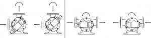
The pumps are typically (when viewed from the shaft end) designed as clock-wise rotation: that is, the sucking mouth (inlet) is on the right and the discharge mouth (outlet) is on the top side.
For reverse operation:
You can operate your pumps in both directions. However, changing rotation direction of the pump shaft changes the pumping direction of the liquid; that is, you can use both mouths of your pumps as the sucking mouth or the discharge mouth. Otherwise, it may not be able to perform the bypass operation.
This pumps have casings that can be turned to eight positions. This allows ports to easily match piping. Relief valve must point to suction port in all cases.