MAGNETIC DRIVEN MODULAR GEAR PUMP
New Solutions
Recorded Accordingto Needs…
Magnetic Coupled
Internal Eccentric Gear Pumps
| PUMP PROPERTIES | |||
| Q | : 1 – 10,5 m³/h | T | : 20 ~ 100 ºC |
| Hm | : 1 ~ 30 Bar | n | : 20 – 1500 d/d |
| Visc. | : 10 ~ 550 cst | ||
Magnetic Driven Modular Gear Pump Types

Product Features
Use Areas
- Safe transportation of corrosive or hazardous chemicals
- Reactive substances such as acids, bases, solvents, isocyanates
- Suitable for explosive atmospheres (ATEX certified types)
- Used in processes requiring hygienic conditions
- Safe transportation of liquid fuels such as diesel, gasoline, and biodiesel
- Leak-proof solution for liquids with risk of evaporation
Material Options
- Pump Casing, Covers: Cast Iron, Ductile Iron, Cast Steel, AISI 316 – AISI 316L SS
- Gears: Steel, AISI 316 – AISI 316L SS
- Bushing: Bronze, Carbon Graphite, Tungsten Carbide
- Sealing: Magnetic Coupling
Working Principles
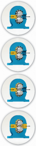
The colored section on the side illustrates the entry of the fluid into the suction port area of the pump body, as well as into the gear cavities of the driving and driven gears. The black arrows indicate the rotation of the pump and the progression of the fluid.
As seen, the fluid transfer occurs between the gears and the enclosing pump body, rather than passing between the gears themselves.
This image represents the state of the pump just before the internal section is filled and the fluid is pushed toward the discharge port. Note how the gear cavities of the driving and driven gears create a sealed pocket for the fluid, ensuring precise volume control.
The next phase depicts the fully filled pump and the process of fluid discharge as it moves toward the outlet. Finally, the fluid is delivered to the discharge port under pressure, driven by the intermeshing gears.