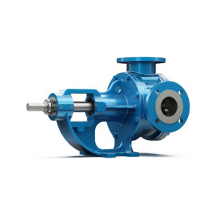
INTERNAL ECCENTRIC GEAR PUMP
Our pumps, used for the transfer of low and high-capacity viscous fluids, serve the global industry.
| PUMP PROPERTIES | |||
| Q | : 0,100 – 250 m³/h | T | : -40 ~ 300 ºC |
| Hm | : 1 ~ 15 Bar | n | : 20 – 1720 d/d |
| Visc. | : 100 ~ 1.000.000 cst | ||
Internal Eccentric Gear Pump Types


Product Features
The Yildiz Pump’s “gear within gear” principle, consisting of only two moving parts, ensures reliable and efficient operation. The secret to the success of positive displacement Yildiz Pompa is the displacement that occurs when the liquid completely fills the space between the rotor and the gear of the idler gear.
As with all gear pumps, the only factor limiting the performance of the Yildiz Pumps is the cleanliness of the pumped liquid. At each revolution of the pump shaft, a certain amount of liquid enters the pump through the suction port and this liquid fills the gap between the rotor and the idler gear.
The crescent on the pump cover regulates the flow of the liquid moving towards the outlet opening. The idler gear rotates on a shaft supported by the pump cover by carrying the liquid between its gear and the inner surface of the crescent. The rotor gear moves between the pump casing and
the outer surface of the crescent and is connected to the pump shaft.
Enjoy reliable and efficient fluid transfer with Yildiz Pompa!
Use Areas
- Transporting viscous products such as sugar syrups, chocolate, honey, and molasses.
- Pumping liquid oils and other food liquids under hygienic conditions.
- Transfer of chemicals such as acids, bases, and solvents.
- Transport of viscous chemicals such as resins, polymers, paints, and adhesives.
- Pumping of lubricants such as fuel, engine oil, hydraulic oil, and grease.
- Processing and transporting viscous products such as creams, lotions, and shampoos.
- Pumping of products such as viscous paints, inks, and coating materials.
- Transfer of additives such as coating liquids.
- High-precision liquid dosing and filling operations.
Material Options
- Pump Cover and Casing: Cast Iron, Ductile Iron, Cast Steel, AISI 316 – AISI 316L SS
- Gears: Ductile Iron, Cast Steel, AISI 316 – AISI 316L SS
- Bushings: Bronze, Carbon Graphite, Tungsten Carbide, Ball Bearing
- Sealing: Packing Gland,Mechanical Seal, Special Closed System, Cartridge Mechanical Seal
Working Principles

The yellow colored portion at side indicates the liquid as it enters the suction port area of the casing and the area between the rotor teeth and corresponding concave area between the idler teeth. The two black arrows indicate the pump rotation and progress of the liquid.
Notice the progress of the liquid through the pump and between the teeth of rotor idler gear. Also, note how the crescent shape on the head divides the liquid and acts as a seal between the suction and discharge ports.
This illustration shows the pump in a nearly flooded condition just previous to the liquid being forced into the discharge port area. Notice how the gear design of the idler and rotor form locked pockets for the liquid to guarantee absolute volume control.
The view shows the pump in a completely flooded condition and in the process of discharging the liquid through discharge port. The rotor and idler teeth mesh, forming a seal equidistant between the both ports, forcing liquid out the discharge port.
Frequently Asked Questions
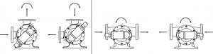
The pumps are typically (when viewed from the shaft end) designed as clock-wise rotation; that is, the sucking mouth (inlet) is on the right and the discharge mouth (outlet) is on top side.
For reverse operation:
You can operate your pumps in both directions. However, changing rotation direction of the pump shaft changes the pumping direction of the liquid; that is you can use both mouths of your pumps as the sucking mount or the discharge mount. Otherwise, it may not be able to perform the bypass operation.
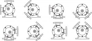
This pumps have casings that can be turned to eight positions. This allows ports to easly match piping. Relief valve must point to suction port in all cases.